LoRa, E-paper, and QR Codes: Making low-power, long-range connected badges

One thing that we can agree on is that QR codes, which originated in Japan, have now reached most of the world, and are used, most probably, way beyond what the inventors at Denso Wave intended—the automotive industry. Another nice invention that probably has outdone the inventors' target is e-paper, the electronic paper. The ones we use in the IoT world are still slow and limited, but still present a lot of opportunities: displays don't necessarily need to be refreshed all the time, and the power savings are great.
Combining both
From price tags to badges, e-paper is a great choice for displays that change only occasionally. So combining QR codes and e-paper sounds like a good match. And if you add LoRa® to the mix, you can have a fleet of self-updating badges in no times. Let's see how.
Required pieces
Hardware
For this exercise, we will need the following hardware:
- A WisBlock device: a full-size base, with a RAK4631 core.
- A RAK14000 EPD Module (we won't be using the buttons for now.) The EPD is connected to the IO slot, which is why we need a full-size base.
- A storage solution to save important data: here I chose the RAK15000 EEPROM Module because that's what I had on hand. We could also go with the RAK15001 Flash Module. The RAK15002 WisBlock SD Card Module isn't a solution, since the IO slot is already taken... But in the end, we just need a way to store a few pieces of data.
Software
We will be using the Arduino IDE as usual, using RAK's Arduino BSP, and a couple of libraries:
- SX126x-RAK4630 for LoRa.
- QRCode to create a QR code.
- The
Adafruit_EPD,Adafruit_GFXandAdafruit_EEPROM_I2Clibraries for the EPD and EEPROM.
We will add some code to draw the QR code from the raw data.
Objectives
We will build a very basic system where a message, sent from a central device (in my case it will be a RAK3172-E evaluation board connected via USB to my Mac), will be received by one or more e-paper-enabled devices, and the QR code displayed along with the name of the holder, and the company's logo.
We will also send individual messages to devices, with a very basic addressing system. To ensure that the content is valid before displaying it, we will send JSON-encoded messages. These are heavier than binary encoded messages, but provide a simple way to ensure integrity and look up key/value pairs.
Basic setup
At startup, we need to initialize a few things: the serial port, so that we can show a log of events; the EEPROM, so that we can get the data we stored previously; the EPD; and LoRa. We will be providing an option to initialize the EEPROM with relevant data for first-time use.
EEPROM
The first thing to look at when connecting several modules on a Wisblock base board is to check which pins they need to check for conflicts. You can look at the schematics but I found that looking at example code, especially in the setup() part, often tells me everything I need to know. And here I had a lot to learn... It turns out that the RAK14000 EDP uses all the available IO pins, from WB_IO1 to WB_IO6. Ouch! Here are the defines for the EPD:
#define EPD_MOSI     MOSI
#define EPD_MISO     -1 // not used
#define EPD_SCK      SCK
#define EPD_CS       SS
#define EPD_DC       WB_IO1
#define SRAM_CS      -1 // not used
#define EPD_RESET    -1 // not used
#define EPD_BUSY     WB_IO4
#define LEFT_BUTTON    WB_IO3
#define MIDDLE_BUTTON  WB_IO5
#define RIGHT_BUTTON   WB_IO6
So if we accept to get rid of the 3-button keypad, we can free up WB_IO3, WB_IO5, and WB_IO6. Since the last 2 are on slot D, let's go with that, and use WB_IO6 for power.
#include <Wire.h>
#include "Adafruit_EEPROM_I2C.h" // Click here to get the library: http://librarymanager/All#Adafruit_EEPROM_I2C

#define EEPROM_ADDR 0x50 // the default address
#define MAXADD 262143 // max address in byte
Adafruit_EEPROM_I2C i2ceeprom;

[...]

void setup() {

[...]

  pinMode(WB_IO6, OUTPUT);
  digitalWrite(WB_IO6, HIGH); // power on for AT24C02 device
  delay(300);
  Serial.println("Power on.............");
  if (i2ceeprom.begin(EEPROM_ADDR)) {
    // you can change the I2C address here, e.g. begin(0x51);
    Serial.println("Found I2C EEPROM");
  } else {
    while (1) {
      Serial.println("I2C EEPROM not identified ... check your connections?\r\n");
      delay(10);
    }
  }
Now, let's assume we have in the EEPROM at address 0x0000 an 8-byte char array that holds the DevEUI. We need to retrieve it and display it (to check all went well):
char buffer[64];
char myUUID[8] = {0};
char myPlainTextUUID[17] = {0};

void readEEPROM() {
  uint16_t addr = 0x0000;
  i2ceeprom.readObject(addr, myUUID);
  Serial.println("myUUID:");
  hexDump(myUUID, 8);
}

// in setup()
  readEEPROM();
  memset(buffer, 0, 64);
  strcpy(buffer, "UUID: ");
  uint8_t addr = 6, ix = 0;
  char alphabet[17] = "0123456789ABCDEF";
  for (uint8_t i = 0; i < 8; i++) {
    char c = myUUID[i];
    buffer[addr++] = alphabet[c >> 4];
    buffer[addr++] = alphabet[c & 0x0f];
    myPlainTextUUID[ix++] = alphabet[c >> 4];
    myPlainTextUUID[ix++] = alphabet[c & 0x0f];
  }
  uint8_t ln = strlen(buffer);
  hexDump(buffer, ln);
In the code above, i2ceeprom.readObject() is a function that reads as many bytes as required to fill the object you pass. Since I am passing myUUID, an 8-byte char array, it will read 8 bytes. hexDump() is a function I wrote to pretty-print hex data. The UUID is also converted to ASCII and put in myPlainTextUUID for later use.
EPD
Now that we have something to display, let's initialize the display, and draw some stuff:
  pinMode(WB_IO2, INPUT_PULLUP); // EPD
  digitalWrite(WB_IO2, HIGH);
  display.begin();
  display.clearBuffer();
  showQRCode(buffer);
  display.drawBitmap(192, 0, rak_img, 150, 56, EPD_BLACK);
  testdrawtext(125, 60, buffer + 6, EPD_BLACK, 1);
  display.display(true);
In this code tidbit above we see a few things: we turn on the EPD module with WB_IO2; the showQRCode function draws a QR code based on the buffer we just displayed in the Serial monitor; drawBitmap() draws a bitmap image, stored in a slightly weird format in a .h file; and testdrawtext.
void drawText(int16_t x, int16_t y, char *text, uint16_t text_color, uint32_t text_size) {
  display.setCursor(x, y);
  display.setTextColor(text_color);
  display.setTextSize(text_size);
  display.setTextWrap(false);
  display.print(text);
}
The showQRCode() function is the meat of the code here: it takes a text, passes it to the QRCode library, and gets back data in a uint8_t qrcodeData[sz]; array. If there was no previous message, ie first-time use, we will skip that.
QRCode qrcode;
uint8_t version = 3;
uint16_t sz = qrcode_getBufferSize(version);
uint8_t qrcodeData[sz];
qrcode_initText(&qrcode, qrcodeData, version, 0, msg);
Once you have that, it's up to you how to display it. The library has sample code that displays it as ASCII art, of sorts. I kept that code, and then converted it to make an image, not unlike the RAK logo. I decided to make each pixel 4 pixels square. Since a byte in the image array encode 8 pixels, I needed 4 bits per pixel, 2 real pixels per byte, rounded up if needed. And 4 x the height of the QR code of course, to make each pixel also 4 points high:
uint8_t myWidth = qrcode.size;
uint16_t qrc_wd = myWidth / 2;
if (myWidth * 2 != qrc_wd) qrc_wd += 1;
uint16_t qrc_hg = myWidth * 4;
uint16_t qrc_sz = qrc_wd * qrc_hg, ix = 0;
unsigned char qrc[qrc_sz];
After that it was easy to assemble the QR code pixels into bytes and lines.
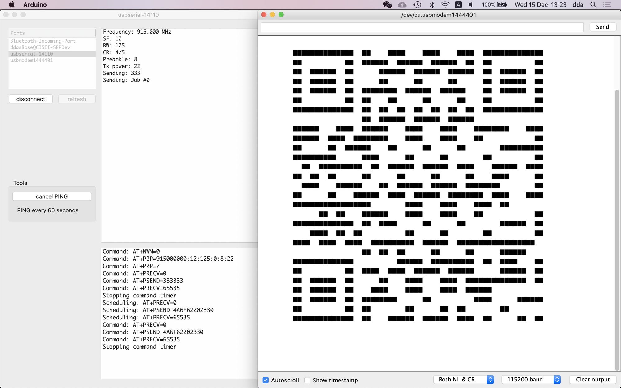
The output in the Serial Monitor
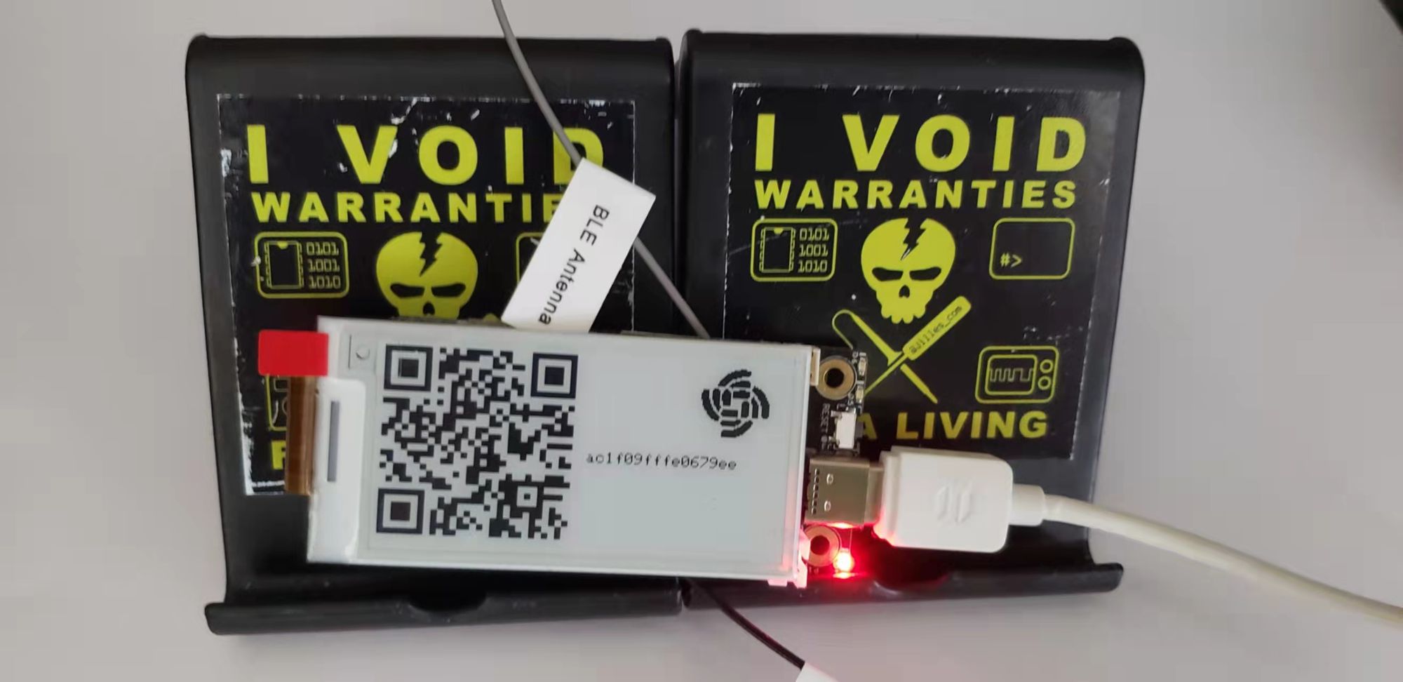
The result
LoRa
The LoRa initialization code is always the same, and shouldn't need any introduction. We will only use reception, for now anyway, so the RadioEvents are set up like this:
  RadioEvents.TxDone = NULL;
  RadioEvents.RxDone = OnRxDone;
  RadioEvents.TxTimeout = NULL;
  RadioEvents.RxTimeout = OnRxTimeout;
  RadioEvents.RxError = OnRxError;
  RadioEvents.CadDone = NULL;
We're now in the loop() event, and wait for a LoRa packet. When it comes in, we do a couple of verifications, and then display the message, after storing it.
void OnRxDone(uint8_t *payload, uint16_t ix, int16_t rssi, int8_t snr) {
  digitalWrite(LED_GREEN, HIGH); // Turn on Green LED
  Serial.println("################################");
  sprintf(buffer, "Message: %s", (char*)payload);
  Serial.println(buffer);
  hexDump((char*)payload, strlen((char*)payload));
  Serial.println("################################");
  sprintf(buffer, "RSSI: %-d, SNR: %-d", rssi, snr);
  Serial.println(buffer);
  StaticJsonDocument<128> doc;
  DeserializationError error = deserializeJson(doc, (char*)payload);
  if (error) {
    Serial.print("deserializeJson() failed: ");
    Serial.println(error.c_str());
    digitalWrite(LED_GREEN, LOW); // Turn off Green LED
    Radio.Rx(RX_TIMEOUT_VALUE);
    return;
  }
  const char* UUID = doc["UUID"];
  sprintf(buffer, "My UUID  : %s\nThis UUID: %s\n", myPlainTextUUID, UUID);
  Serial.println(buffer);
  if (strcmp (myPlainTextUUID, UUID) == 0) {
    const char* msg = doc["msg"];
    sprintf(buffer, "Message: %s", msg);
    Serial.println(buffer);
    showQRCode(buffer);
    display.drawBitmap(192, 0, rak_img, 150, 56, EPD_BLACK);
    testdrawtext(125, 100, (char*)msg, EPD_BLACK, 1);
    display.display(true);
  }
  digitalWrite(LED_GREEN, LOW); // Turn off Green LED
  Radio.Rx(RX_TIMEOUT_VALUE);
}
The message is sent as a JSON packet, so the first thing to do after displaying it – and that is just for debugging and explanation purposes: we shouldn't display it at all unless it's for this device – is to decode it, and if it fails, abort. Then we extract the UUID value, and compare it with our myPlainTextUUID (told you it would come in handy). If it's the same, we get the msg value and display it as a QR Code and plain text.
That's about it. We have now a simple system to page badges. There are of course missing parts. First is the writing the DevEUI to the EEPROM. This is covered in this Github repository, where the README is almost a blog post, and quite detailed.
Then there's sending the JSON packets from a computer, or other IoT device. This is beyond the scope of this blog post, but quite easy to implement. I will write a post separately demonstrating how to send JSON packets in different ways.