

LoRa Alliance® Introduces Relay Feature

How the amendment to the LoRaWAN Standard helps expand network coverage and capacity.
LoRaWAN networks have been around for quite some time, there are already large-scale deployments on a global level. Technology has proven itself and it is here to stay. This being said, it is in no way ideal, as is the case with any network, and there are inherent issues that need solving.
As LoRaWAN utilizes gateways to relay end-device traffic, sometimes it is not cost efficient to invest in additional ones being deployed to fill out dead zones in the coverage area. This is especially true when there are only a few nodes that need to be serviced, for example in a remote area, which makes it hard to justify the investment cost. LoRa, being very long range, power efficient and having small data payload size is quite well suited to utilize Relays, to remedy this issue.
The use of Relays and their introduction to the standard would allow a reduction in infrastructure CAPEX costs, especially at the edge of the network, while providing stable coverage for mission critical applications where consistent coverage is a must.
Requirements
In order for this amendment to the LoRaWAN Standard to be an efficient one, there are requirements that need to be set. End-devices should adhere to these in order to provide sufficient quality of service:
- Low power & low cost
- Architecture equivalent to a LoRaWAN end-device
- Battery powered
- The relay is capable to handle at least 10 LoRaWAN end-devices
- The relay appears as a standard LoRaWAN end-device
- The relay is secure as a LoRaWAN end-device
- End-devices working under a relay shall be capable to revert back to traditional LoRaWAN configuration
Use Cases
Two main use cases come to mind when talking about the benefits of using a Relay Node.
1. Relaying data to a device obstructed by material that heavily attenuates RF waves. For example, behind a very thick wall, in a metal container (for storage, refrigeration, etc.), or in a buried one and/or in foliage. These conditions attenuate the signal heavily so a relay close to the end node would have sufficient range to pick-up the low-level signal and translate it to the gateway.
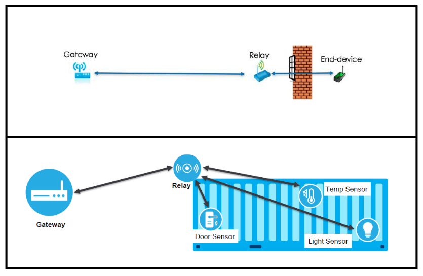
2. Areas with sparse, low concentration of sensors at the edge of the network where investing in deploying a gateway is not cost efficient. This is a great solution to expand network coverage, especially in cases where data volume is low and the node can operate as a relay part of the time and as a regular node the rest of the time, forwarding its own measurement data. This would introduce additional coverage at no additional cost.
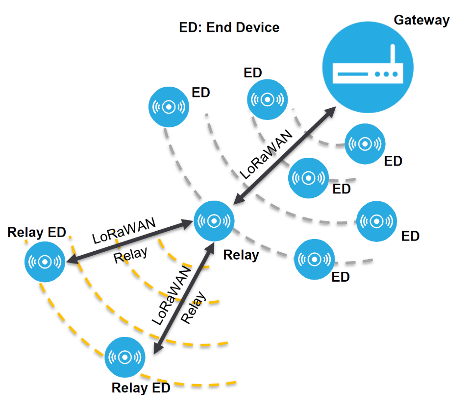
Principle of Operation
To put it simply, as the End-node cannot reach the gateway it relies on the Relay-node to forward its Uplink Frame. Thus, the end-node uses one communication channel to send its frame to the Relay, where the Relay uses a second one to forward to the gateway.
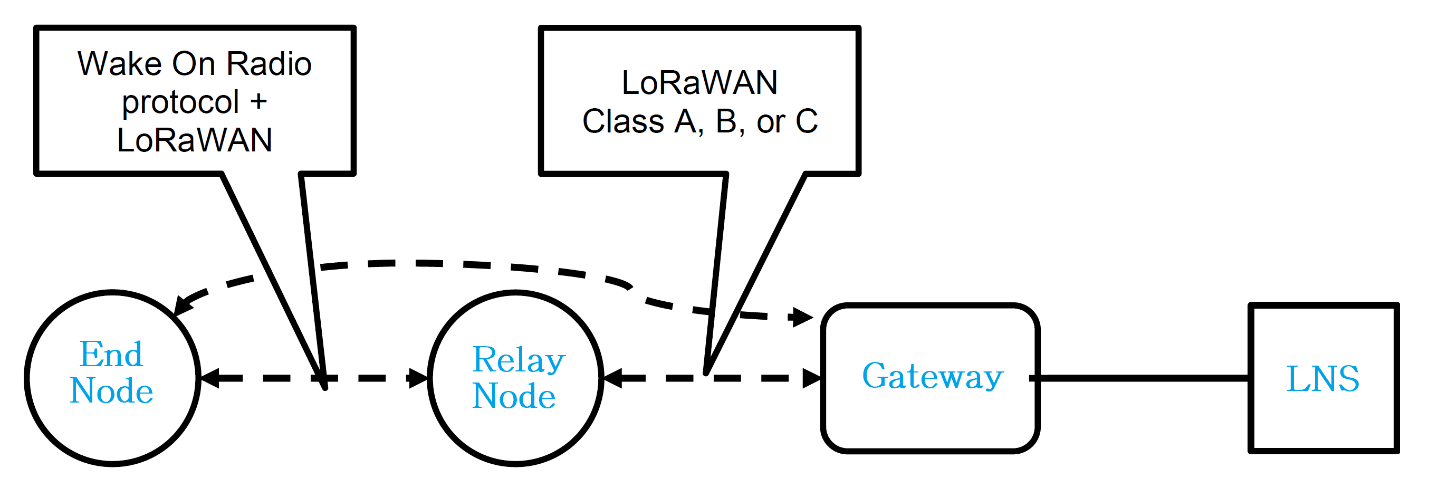
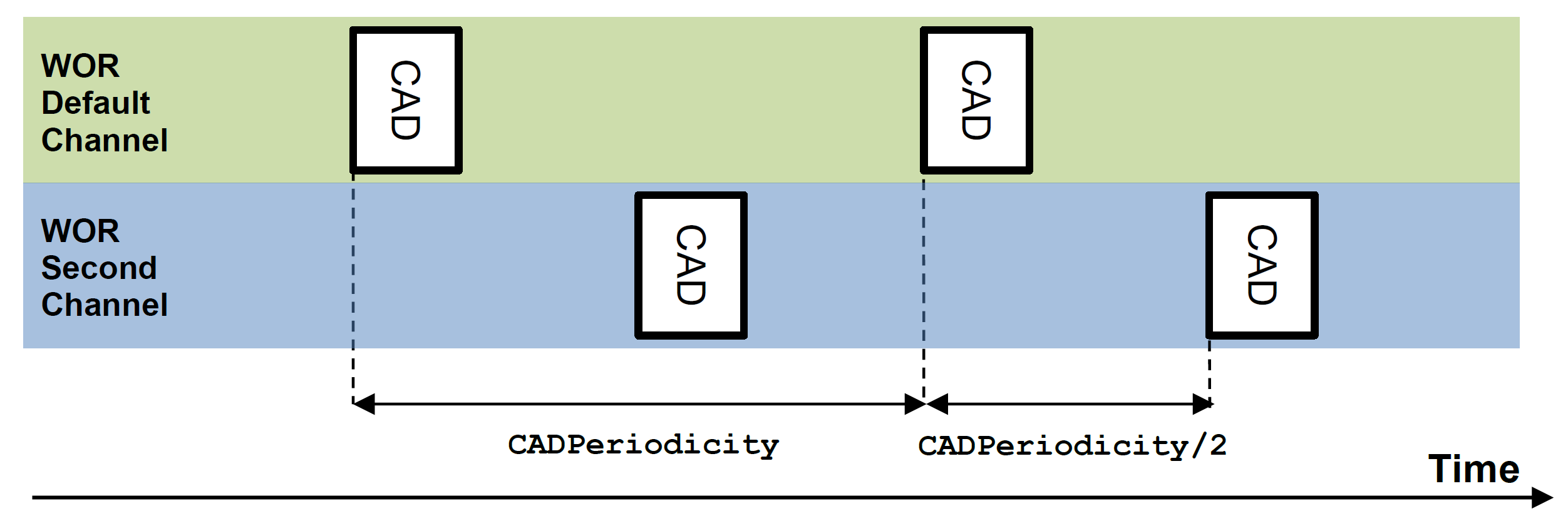
In order for a Relay to function efficiently it needs to monitor for incoming traffic from End-nodes. Thus, a mechanic called Channel Activity Detection (CAD) is defined, where two channels are monitored for activity:
- 1 mandatory channel with a predefined Frequency and DR:
- SF10 BW500 in the US and Australia (US915 and AU915 bands)
- SF9 BW125 (EU868/AS923/…)
- 1 channel is free to be defined by network operators
- the CAD goes from 25ms to 1s (default)
In order for the CAD to work a new time frame is introduced called Wake On Radio (WOR), together with Wake On Radio Acknowledge (WOR ACK). The first one has the purpose of waking up the Relay and signaling the parameters of the LoRa frame to follow. At this point the Relay sends a response in the form of a WOR ACK frame in order to synchronize with the End-device and provide it with forwarding information, which consists of:
- Data rate between Relay and NS
- Relay XTAL accuracy
- CAD periodicity
- Toffset
- CAD To Rx delay
- Forward capacity
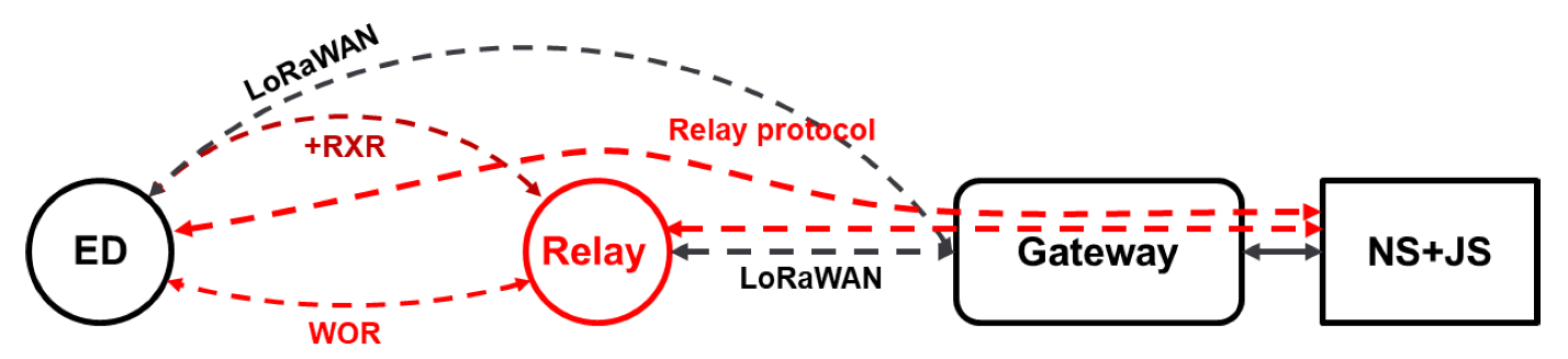
As it can be seen in the following figure there are quite a few new elements in the communication stack compared to an end-node to gateway transmission (marked in red), so a more detailed explanation is required and is depicted in the chapters to follow.
Message forwarding
Basics
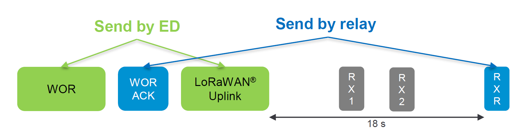
It all starts with a WOR frame from the End-node requesting the Relay to wake up in order to forward the subsequent Uplink Frame. The Relay responds with a WOR ACK, setting up the parameters for the actual data Uplink. At this point the End-node has complete information and is able to send the LoRaWAN Uplink Frame to be received by the Relay. This is an oversimplified explanation of the procedure, we are going to go into detail and explain the Uplink and Downlink separately.
Uplink/Downlink
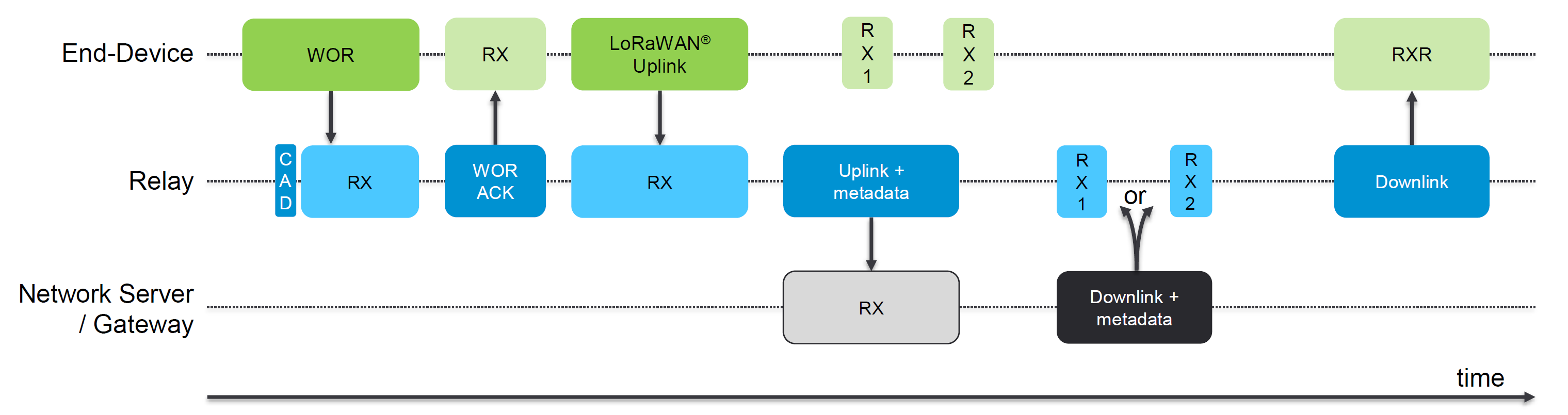
Now that we have covered the basics, we can discuss how Uplinks and Downlinks are processed. The figure above is a more detailed diagram of the message forwarding process and will be referred to for both the End-device and Relay operation. Let us go in order of the frames being generated and processed to gain a better understanding of what it takes for a LoRa Frame to be forwarded from the End-node, throughout the Relay to the Gateway and LNS.
Uplink from the End-Node
- The End-device sends a WOR frame in order to wake up the relay for reception of the actual LoRaWAN Uplink Frame.
- The Relay is in CAD mode and it detects the WOR frame, this causes it to respond with a WOR ACK, setting up the transmission parameters between the Relay and End-node.
- The End-received the WOR ACK in its RX window, which lets it know the Relay is ready to receive the actual LoRaWAN Uplink frame, which it sends at this point.
- The Relay receives the LoRaWAN Uplink frame in its RX window.
Uplink from the Relay
- At this point the End-node has transmitted its two Uplinks (WOR and LoRaWAN frames) and it is waiting for a downlink.
- The Relay now has the End-node LoRaWAN Frame and it needs to relay the information to the Gateway. It sends a LoRaWAN frame to the Gateway containing the Uplink (dedicated FORT 226 only) + Metadata (RSSI/SNR/DR and WOR channel)
Downlink from the Gateway/LNS
- The Gateway/LNS receives the Uplink from the Relay in its RX window on dedicated port 226, processes it responds with a Downlink + Metadata frame.
Downlink from the Relay
- The Relay receives the Downlink from the Gateway in its RX1 or RX2 window and forwards it to the End-device
- The End-device receives the Downlink from the Relay in its RXR window. The RXT windows is 18 second after the initial LoRaWAN Uplink in order to allow for both the Relay and Gateway to respond It utilizes the WOR frame data rate, however the frequency is that of the LoRaWAN Uplink still.
Security
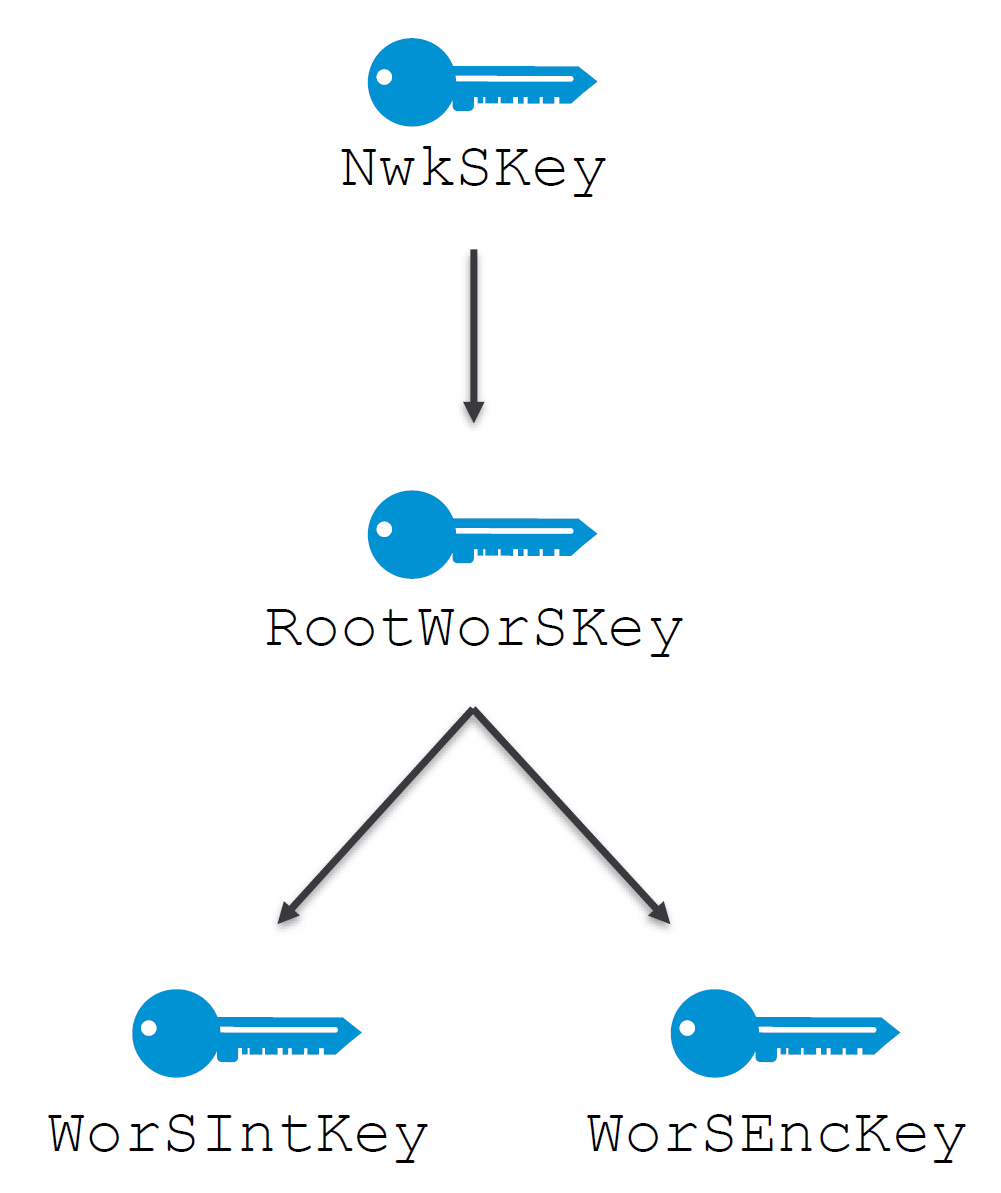
In order for the data to reach the LNS there are 2 separate RF channels that are formed: End-Node to Relay and Relay to Gateway. Thus, there are going to be 2 separate sessions and 2 separate sets of keys, this will preserve the security level. This way the Relay will not be able to decrypt the actual data payload, only the Gateway will, which is how proper LoRaWAN communication should be handled.
The following keys are specific for the End-Device to Relay link and are not used for the actual payload data. This preserves the security of the link and at the same time does not allow the Relay to decrypt the payload data (security risk).
Root Relay Session Key (RootWorSKey)
A session key that is utilized to compute the WorSIntKey and WorSEncKey.
For OTAA activation it is derived after receiving a valid Join-accept frame
For ABP activation it is pre-provisioned in the End-devices together with the WorSIntKey and WorSEncKey.
WOR Integrity Session Key (WorSIntKey)
WorSIntKey is used for both the End-node and Relay to verify the MIC of WOR and WOR ACK frames, which evaluates frame integrity
WOR Encryption Session Key (WorSEncKey)
WorSEncKey is the security session key used to encrypt and decrypt the WOR and WOR ACK frame payload.
Battery life
This is perhaps the most interesting part of this article, as it is what would impact the usability of the Relay node the most. With additional functionality comes additional power consumption, this is to be expected, however the question is would it still be worth it? Would the ability to forward data from distant nodes impact battery life so much as to make it impractical for a real deployment? this is the question we will be answering in this section. Take note that the following data is provided by Semtech and is not a test in a large-scale deployment, so real numbers might vary.
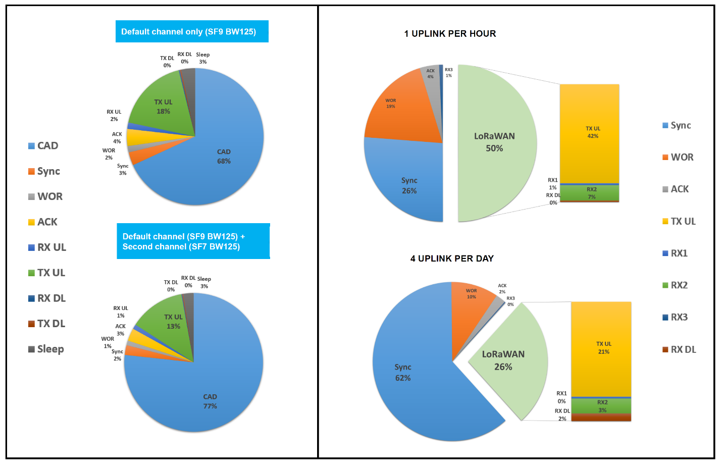
The image below is a depiction of the expected battery life for a node based on the Semtech SX1261, with the following parameters.
CAD every 1 second with 10 end-devices utilizing the following configuration:
- send 50 bytes every hour
- receive 20 bytes once per day
- SF9 BW125 for WOR and LoRaWAN® both
- ±30ppm XTAL error for both nodes
- Battery capacity 17Ah (1x SAFT LS 33600)
There are 2 main points that one can take from the Pi chart:
- 60 to 80% of the power consumption is due to the CAD mechanics, as is to be expected. Running a node in Relay node leads to an average power consumption of a 3x to what it would be all things being equal if the node is working as a regular class A End-device.
- Utilizing 1 default channel (top chart), compared to 2 default channels (bottom chart), does not significantly impact battery life. Thus, it is more than worth it to utilize 2 channels as it will result in a much higher chance of data forwarding, at a relatively low cost in terms of power consumption. This is expected to be the preferred mode of operation for Relay nodes.
- In this particular case the expected battery life is 10 years with 1 channel and 7.5 years with 2 channels. This is utilizing a very large battery of 17Ah, which is frankly not the case for many applications. If we adjust the numbers for a more widely used 2700mAh, battery life comes at about 1 year for a 2 channel Relay, up to 1.5 years for a 1 channel Relay. While this is not a significant increase it is more than a fair amount, considering it might eliminate the need of a gateway or at the very least provide a transition period of at least a year for network coverage to be improved. Something that can be done via a simple OTA Upgrade having such a large impact on coverage is no small feat, not to mention that a mains powered node or one that has energy harvesting could work in this mode indefinitely.
In summary battery life is, as expected, shortened to a large extend if a node works as a Relay, however it is not below the 1-year mark. This combined with the fact that it can extend coverage and capacity at no additional network infrastructure cost makes it an overall efficient solution, where the benefits outweigh the negative aspects (at least in the opinion of the author).
Takeaways
- LoRaWAN keeps responding to market demand to further simplify adoption and lower cost barriers
- A Relay is low power, low cost and secure as End-device
- The LoRaWAN ecosystem has now an efficient standardized solution to extend reliable coverage to small cluster of devices at the very edge
- With Relay, satellite connectivity in remote areas becomes affordable also for indoor use cases

