Work in a Well-lighted Environment. Measure the Lux with Wisblock

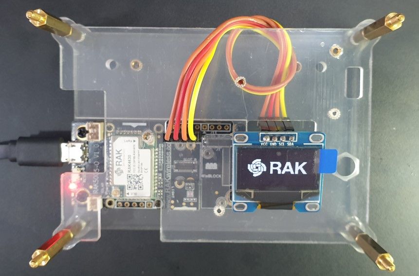
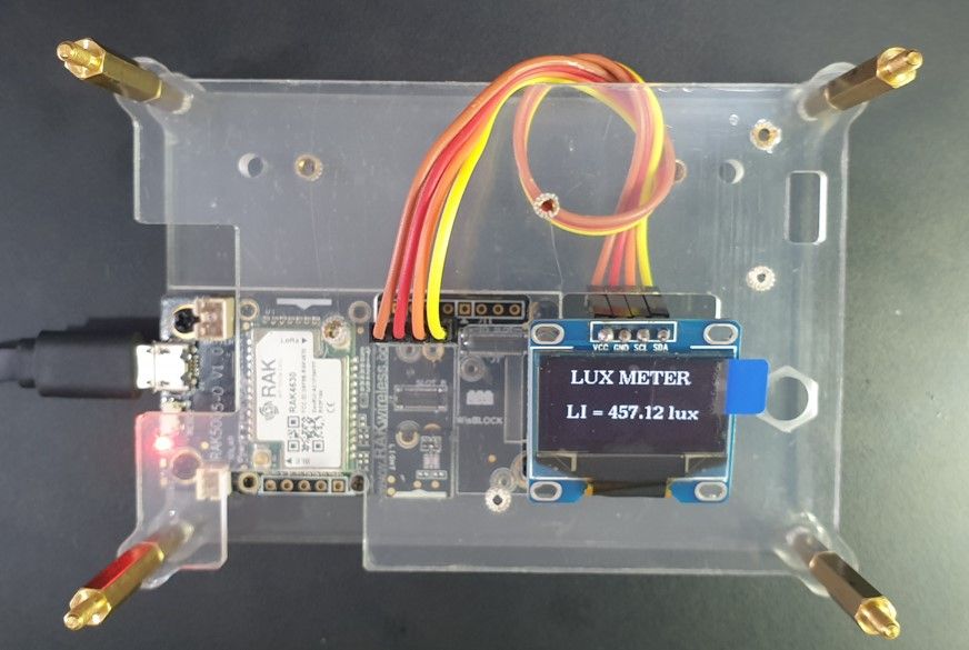
Good lighting in our working areas is crucial since it affects our productivity and safety concerns. The benefit of adequate light levels is to prevent eye strain which allows you to work efficiently and comfortably for longer periods. This article will guide you on how to build a lux meter using the Wisblock platform to measure light levels of your workplaces. See figure below for reference build.
Based on EN 12464 Light and lighting-Lighting of workplaces, recommended light levels of various places are indicated in the table below:
| Work Areas | Luminous Intensity (lumen/m2) |
| Homes and warehouses | 150 |
| Common office work area | 250 |
| Classrooms | 300 |
| Common office work | 500 |
| Common drawing areas | 1000 |
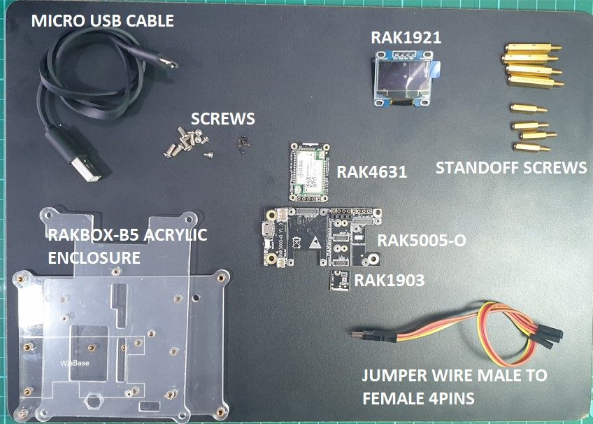
If you want to build your lux meter using Wisblock here are the parts list:
- RAK5005-O WisBlock Base Board
- RAK4631 nRF52840 SX1262 Module for LoRaWAN
- RAK1903 WisBlock Ambient Light Sensor
- RAK1921 WisBlock OLED Display
- RAKBox-B5 Transparent Acrylic Enclosure
- Jumper Wire Female to Male
- Micro USB cable
- 2.54mm Single Row Male Header Connector 4pins
- 2.54mm Single Row Female Header Connector 4pins
- Screws
- Arduino IDE
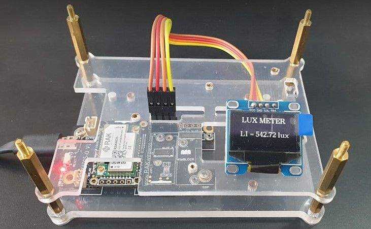
How to build Lux Meter using Wisblock Platform
Below are the parts list used to construct the Lux Meter Wisblock.
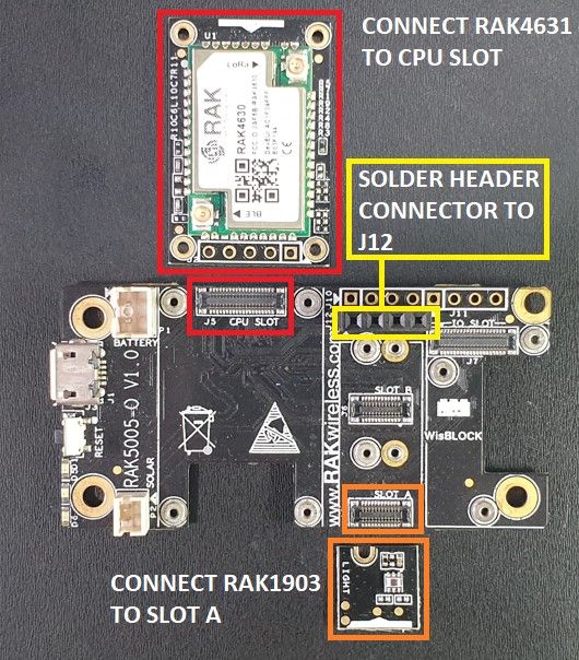
2. Connect the RAK4631 to the CPU slot and solder a 4pin female header connector to J12 then attach the RAK1903 to slot A.
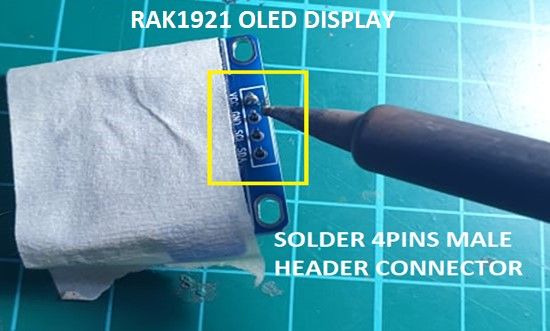
3. Solder a 4pins male header connector to RAK1921 OLED display. Make sure to cover a masking tape on the OLED display to prevent excess solder lead from coming from the pins. Excess solder will damage the OLED display.
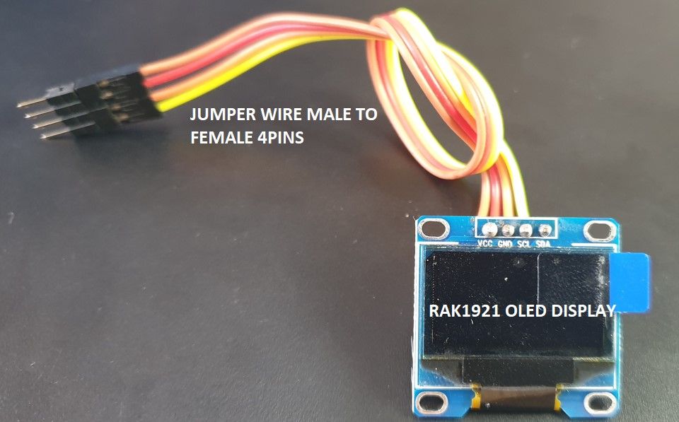
4. Attach the 4pins male to female jumper wire to the RAK1921. Be careful to check the supply polarity pins so that the OLED display will not be destroyed.
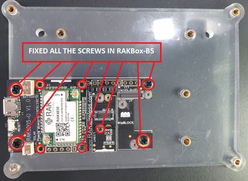
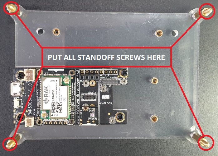
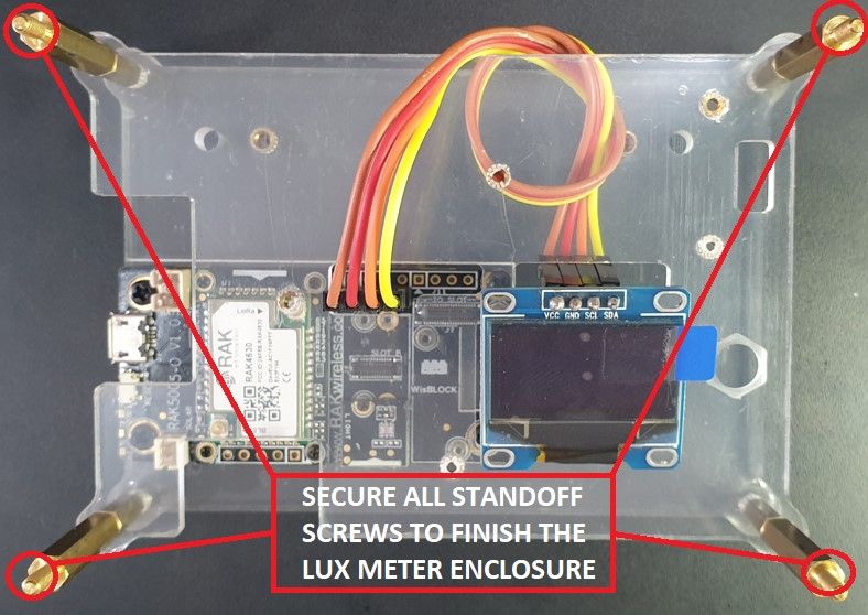
5. Fix all screws in the RAK5005-O and RAKBox-B5 acrylic enclosure. Put all the standoff screws so that the top acrylic enclosure will be secured.
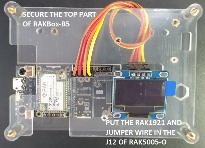
6. Secure the top part of RAKBox-B5 and put the RAK1921 wire assembly in the J12 of RAK5005-O.
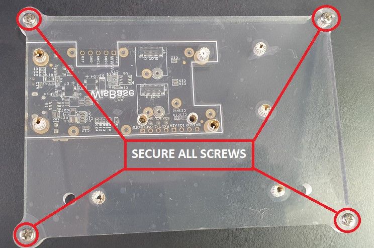
7. Fasten all the standoff screws in RAKBox-B5 Transparent Acrylic Enclosure.
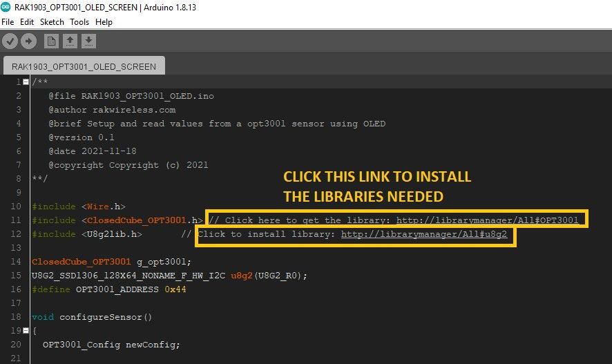
8. Download the code from this link. After downloading, open it using Arduino IDE. Install the RAKwireless Wisblock Core modules for the Arduino Board manager using this link. After installing, add all the libraries by clicking the link of OPT3001 and U8g2 in the Arduino code. After completing all the requirements, check the code by compiling it and then upload the code in the RAK4631 nRF52840 SX1262 Module for LoRaWAN.
9. After uploading the code, you can now test your Lux Meter project in your room or office to measure the light levels in your area if adequate.