Prototyping: How To Make A Clean and Compact Connection with Wisblock

Understanding the WisBlock Connectors
If you are using or planning to use WisBlock modules, understanding the interconnections of these modules is very important. I will discuss in this article all the necessary details you need to know about the WisBlock connectors – the important resources, its pinouts, possible conflicts and things to look out for, as you start your WisBlock journey. Surely, having enough knowledge and information about the WisBlock connectors will definitely help you have a smooth and optimized WisBlock experience.
The Basics - WisBlock Connectors
WisBlock is designed to make your life easy by creating clean and scalable IoT prototypes. You cannot achieve this goal by using standard headers that will usually get loose connections. Aside from that it doesn’t look elegant, it will likely cause you headache along the way.
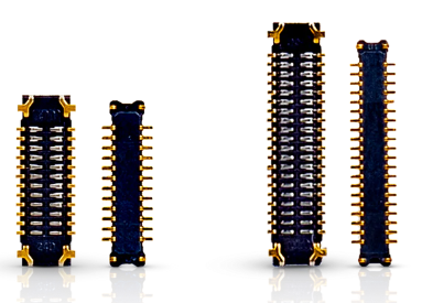
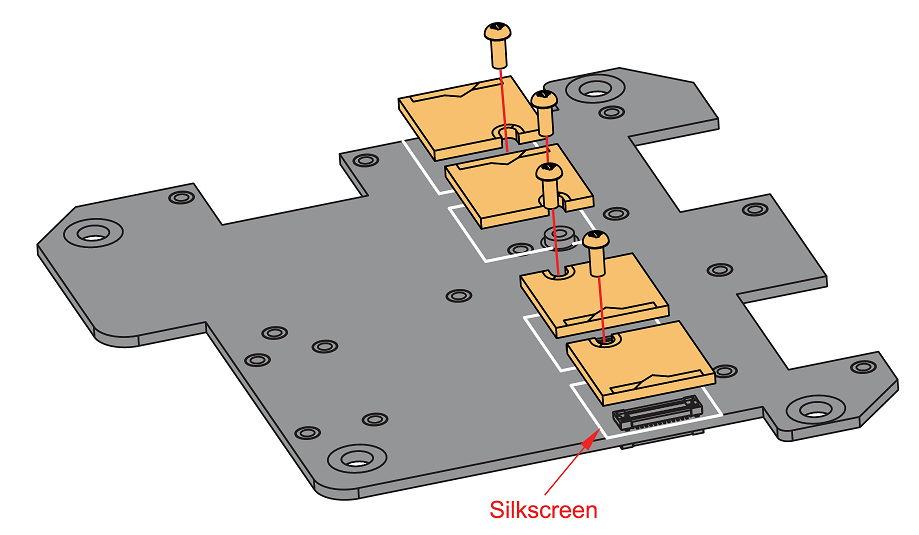
That is the reason why WisBlock connectors are based on board-to-board type that can be secured by screws. It is immune to vibrations, has good electrical coupling and doesn’t occupy too much space. It is a reliable solution and surely a good looking modular IoT hardware platform. We offer these connectors and the necessary screws in RAKwireless web store so you can easily purchase it without needing to put effort in searching on electronic parts distributors.
However, the WisBlock connector is not all perfect. There are few negative side effects on choosing this connector like incompatibility to other popular modular hardware, hard to solder and can be physically broken with improper and careless mounting. To compensate for these limitations, we offer WisBlock Interface modules that have standard headers so that users can still use this method if needed to. We also exposed standard header pins on bigger WisBlock Base boards. And also, you can use interface boards that make WisBlock compatible to other modules like Groove and Qwiic based modules. Still overall, we believe that the WisBlock approach is needed in creating an alternative way of building IoT hardware prototypes.
24-pin and 40-pin
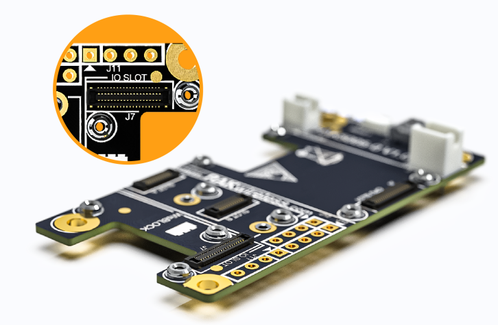
There are two variants of WisBlock connectors you can see on a WisBlock Base board, 24pin and 40pin connectors.
The 24-pin is used on the so called Sensor Slot and with names Slot A to F depending on the WisBlock Base board you have. Some WisBlock Base boards have two of these sensors' slots, some have four or even up to six. This 24-pin connector is used on small sensor modules. The 40-pin WisBlock connector on the other hand is used on the WisBlock Core (CPU Slot) and IO Slot compatible modules. These obviously have more available pins for interconnections.
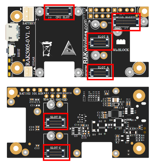
Always remember that when the word Sensor Slot is used, it is usually referring to the 24-pin WisBlock Connector. On the other hand, if IO Slot is used, it refers to the 40-pin connector.
Regardless of the connector, either 24-pin or 40-pin, having the knowledge on what signal is available on both is very essential on your WisBlock development. Without this knowledge and know-how, you are prone to encounter messy conflicts as you combine various WisBlock Modules.
Pinout Details
Efforts are made to ensure that there are enough pins to be used on WisBlock platform. As a WisBlock user, it must be clear to you what are the pinouts available at your disposal. You can check the distribution of WisBlock connectors pinouts on the specific WisBlock Base board datasheet. There are many different WisBlock Base boards but the connector principles are the same.
Let’s discuss first the 40-pin Wisblock connector which is used on WisBlock Core, IO Slot and Power Slot. I will not focus on each individual pin. However, looking at the pin labels, you will see how many IO pins are available.
These are the key takeaways on 40-pin WisBlock connector:

- It is the standard connector (meaning the pin assignment is the same) for WisBlock Core, IO and Power slot. Being used as the connector for WisBlock Core, it is very important that you are familiar with the pinout of this connector.
- These are all the pins you can pull out from the MCU (microcontroller) of the WisBlock Core. Even if the MCU has more IO pins available, the 40-pin WisBlock connector will be the limitation.
- The PCB trace of 40-pin connector is shared on other slots with the same name. For example, pin number 32 of IO slot (assigned to IO4) is shared to the IO4 of another slot (whether Sensor slot or IO slot). So remember that if one module is already using an IO pin (IO4 in this illustration), the other IO module should not use this same IO. Otherwise, it can result to conflict. Some pins are ok to be shared through like the I2C bus.
- All of the serial communication mode available for WisBlock platform is accessible in the 40-pin connector – UART, I2C, SPI and USB. Physically, there are two UART lines and two I2C bus available but that depends on the WisBlock Core you use if anything is present in that pin. You have to double-check it from the datasheet of the WisBlock Core. Also, even if there are two common serial buses like for I2C, it still depends on the firmware you use if it supports it. For example, if you use RAK4630 with RUI3 firmware, it only supports I2C_1 bus with Wire.begin() and the seconds I2C bus I2C_2 will not work even with Wire1.begin().
After knowing the necessary info about 40-pin connector, you can proceed on checking the 24-pin connector (usually used on Sensor Slot). It is a bit different from its bigger brother and introduces another layer of complexity. There are at least sensor two sensor slot in a WisBlock Base board (up to six sensor slot to bigger Base boards) and because of its limited pinout, there are module combinations that is not possible like having more than two WisBlock Modules that uses UART.
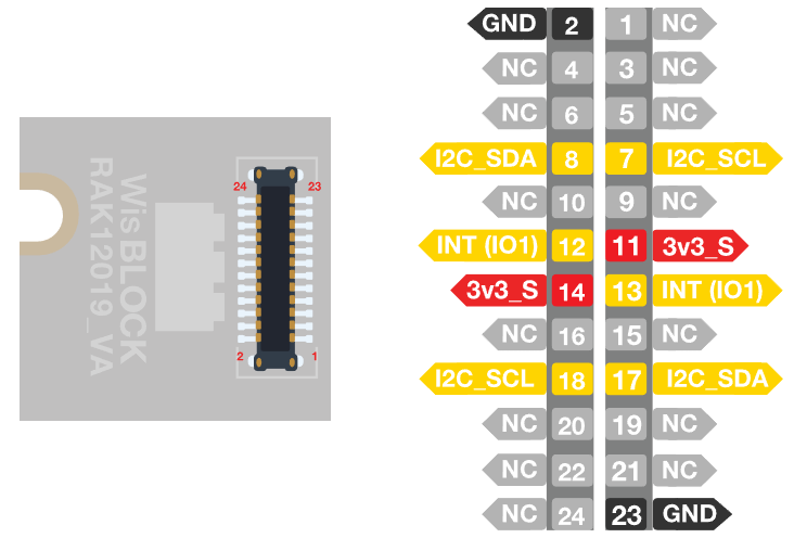
When working on the 24-pin connector, you need to be familiar on both sides – WisBlock Base board and WisBlock Module.
Some important details on 24-pin connector pinout:
1. Each WisBlock module has a pinout diagram illustration in its datasheet. This enables you to quickly see what connections are used in that module – does it use IO/I2C/UART/SPI? You can also look at the schematic to get full details.
2. Most modules that plug in to the Sensor Slot are based on I2C. The primary reason is that I2C device can share common bus. Even if you max out six modules in all Sensor Slots, as long as these are I2C, there will be no issues (assuming no common I2C address).
3. Sensor Slots has two power sources – the standard supply 3V3 and the configurable 3V3_S. The voltage level of these supplies is 3.3V but the second one (3V3_S) can be disconnected via an IO pin from the WisBlock Core. The IO pin that controls 3V3_S is IO2. This means that extra care is needed if the module uses 3V3_S as supply because it has to be controlled by the IO2 pin. This feature is implemented to achieve maximum power saving possible. You can totally disconnect the power connection of the module via IO2 of the WisBlock Core.
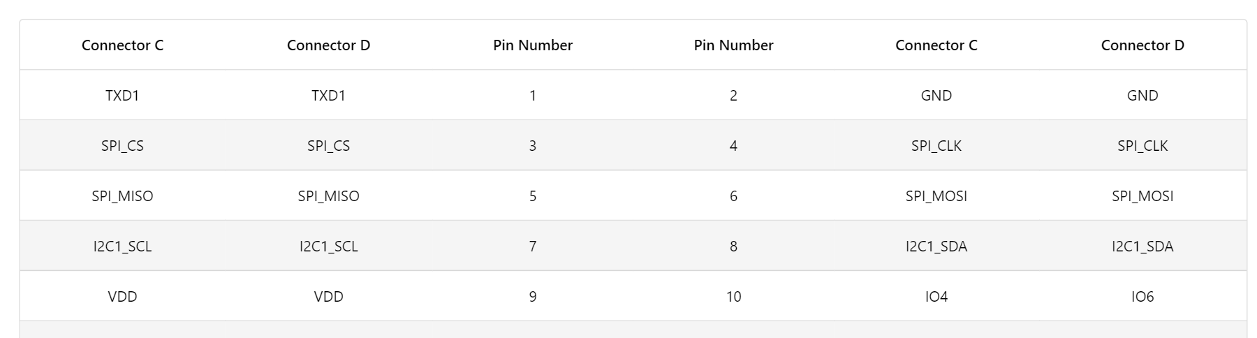
4. Looking at the Sensor Slots schematic of the WisBlock Base board, the 24-pin connector is designed to support two IO pins, one UART, one I2C and one SPI. Extra care is needed on IO pins and UART.
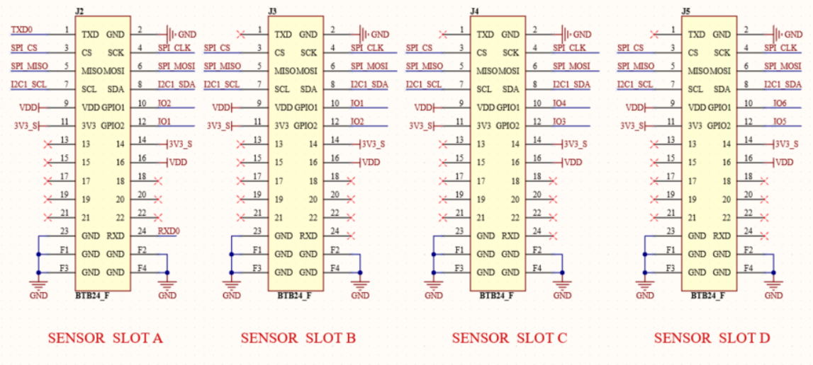
The IO pins assignment is not the same for all WisBlock Base board Sensor Slots so you have to be vigilant on the specific IO pin needed by the WisBlock Module. To make it easier, there is a table in the datasheet of the WisBlock module that guides user what IO pin to use on specific Sensor Slot.
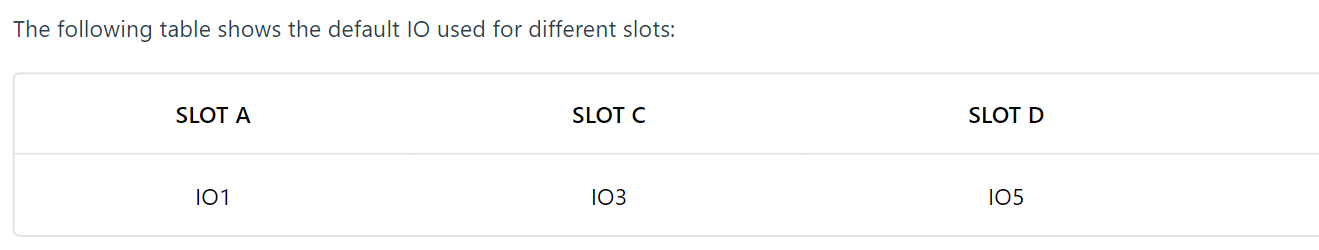
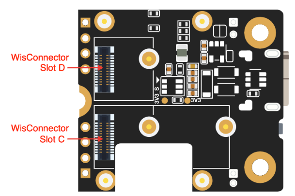
6. On WisBlock Base boards, UART is limited to few Sensor Slots depending on the type of WisBlock Base board used. To illustrate, RAK19003 has UART lines on both Slot C and Slot D. But on RAK5005-O, UART is only available in Slot A. This information can be found on WisBlock Base board datasheet as well as a table for pinout assignments.
7. WisBlock IO2 pin is special. As mentioned in item #5, it controls the connection of power supply 3V3_S to the sensors slots. This means that it is used as an output pin which controls the MOSFET that cuts the 3V3_S line in the WisBlock Base board. Even if it has that purpose, IO2 is still connected to Slot A and B of WisBlock Base boards. With this information, you have to be careful when putting modules in Slot A and B and ensure that there will be no unnecessary interaction possible with IO2.
Final Words
WisBlock is designed to make things easier to integrate, prototypes at lowest power possible and ensure that the IoT device is ready to be deployed reliably. However, without clearly understanding of the WisBlock connector, it will be really hard to achieve these goals and users might face conflicts as it develops solutions using WisBlock. Overall, we believe that using these connectors is the innovation needed to produce a ready and reliable IoT prototype.