Tips on Getting Started with RAK Commercial Gateway LoRa Server

All RAKwireless Commercial Gateway devices come with an integrated LoRa Server. This turns what is a simple Packet Forwarder into a complete LoRaWAN Network solution.
The LoRa Server expands the capabilities of the Gateway so it can monitor traffic locally, visualize network load, list active devices and their behavior, show duty cycle loading, etc.
Having this functionality available raises the bar on what one could do with the LoRaWAN Gateway. The user gets all the packet metadata, the decrypted payload is visible and you can easily observer the network behavior via the web based visual UI.
Additionally, one can extend the functionality even further by integrating one or more external gateways and aggregate the data in the LoRa Server.
This can than be built on top of by creating custom encoders/decoders or bridging the data to an off-site Application server.
New to LoRaWAN and LoRa Server?
The built-in LoRa Server is well suited for both testing use case scenarios and integration with existing deployments of nodes and Gateways. It is a great starting tool to learn and develop your own LoRa Network
So, what do you need to do in order to reap the benefits of these features?
Step 1: Switch to working in the Built-in LoRa Server mode
First and foremost, you need to configure the Gateway to act as a LoRa Server, not just a Packet Forwarder, as is the default setting. To switch between modes, go to the following sub menu (Figure 1)
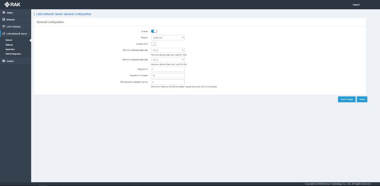
Figure 1 | Protocol selection
LoRa Gateway → LoRa Packet Forwarder → Protocol
You should use the drop-down menu to switch to the Built-in LoRa Server.
Step 2: Enable the LoRa Network Server
This is done in the General tab of the LoRa Network Server menu. Simply press on the slider to turn it on/off (it is on, when blue). It is mandatory to choose your Region from the menu, make sure this is in line with the allowed bands at your location.
The following parameters can be adjusted or left with their default values (they should be within norm). See Figure 2 for reference:
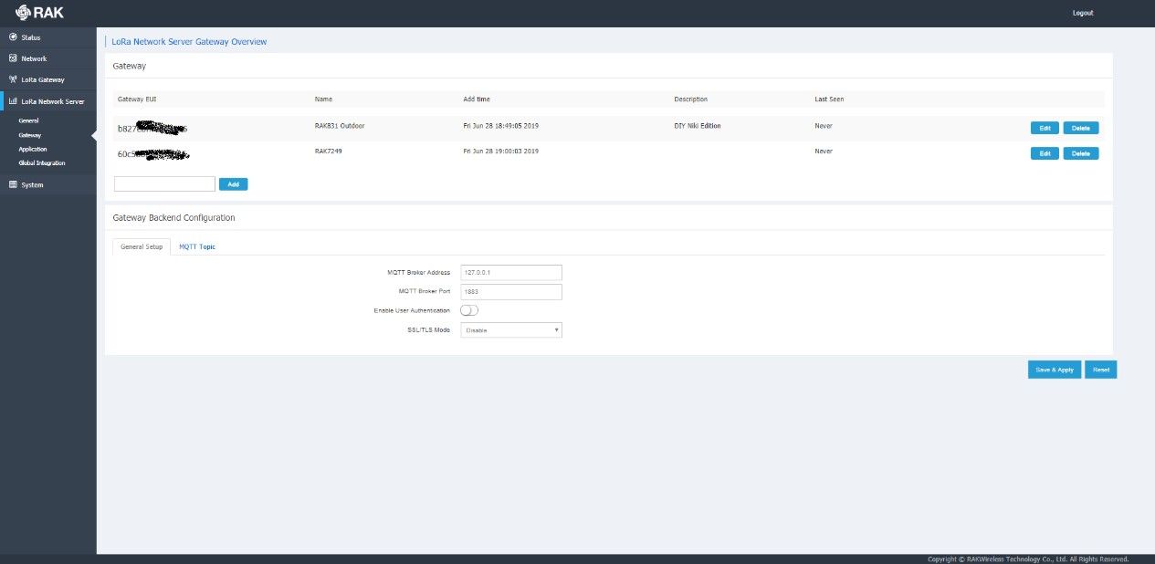
Figure 2 | Enabling the LoRa Server
Adaptive Data Rate (ADR)
You can set you minimum and maximum data rates depending on whether you want to use (ADR) or not.
Network ID
The ID of the network to be advertised to end devices in case you want to have roaming to other networks.
Downlink Tx Power
The power in dBm the Gateway will be transmitting with (make sure you adhere to local limits).
Device-status request interval
The time in seconds, over which the Gateway sends a status request downlink. Enter 0 to disable it (default).
Step 3: Adding additional Gateways (Optional)
In this section you can add and External Gateways to work with your LoRa Network Server. This way packet forwarded by the listed Gateways will be forwarded as though they were within the range of this device.
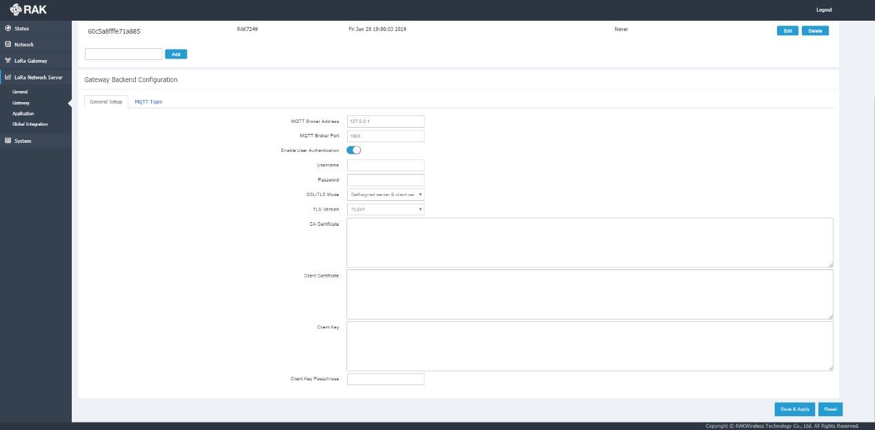
Figure 3 | Adding Gateways
You can configure the Gateway Backend Configuration in order to point the Gateway to an external MQTT Broker. However, this feature is beyond the scope of this article, as it implies, the data will be handled externally.
Step 4: Application
In order to have your nodes be authenticated and to see the decrypted data you need to have an Application created. Simply enter a name in the text field and press the “Add” button.
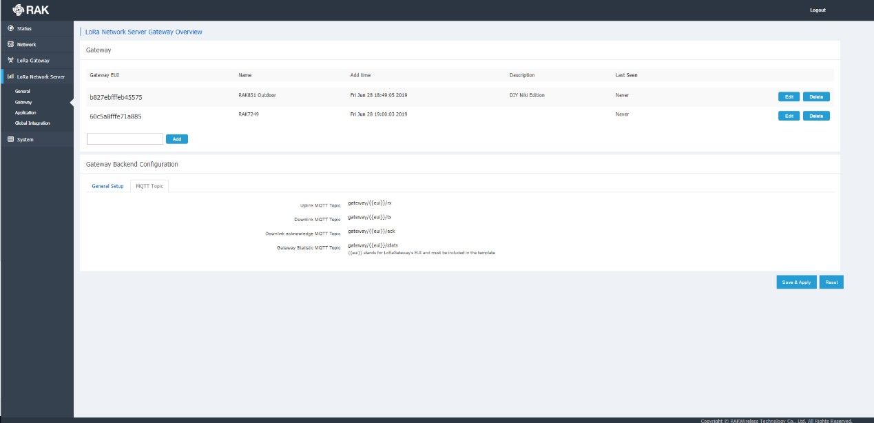
Figure 4 | Application creation
You will be redirected to the main Application screen, where you need to you can start adding Devices to you Application or Change the Application Configuration (Name and Description)
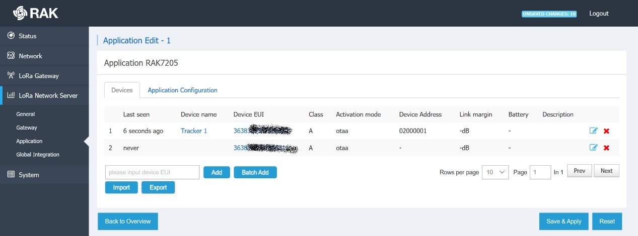
Figure 5 | Main Application screen
Simply input a valid Device EUI and press the “Add” button (you can also do this in batch).

Figure 6 | Adding a Device
You will be redirected to the Device Configuration screen where you need to enter the following:
Name:
This is up to your choice
Class:
Class A and Class C are supported
Join Mode:
OTAA and ABP are both supported
Application Key:
Make sure you input a valid Key (this can also be generated randomly)
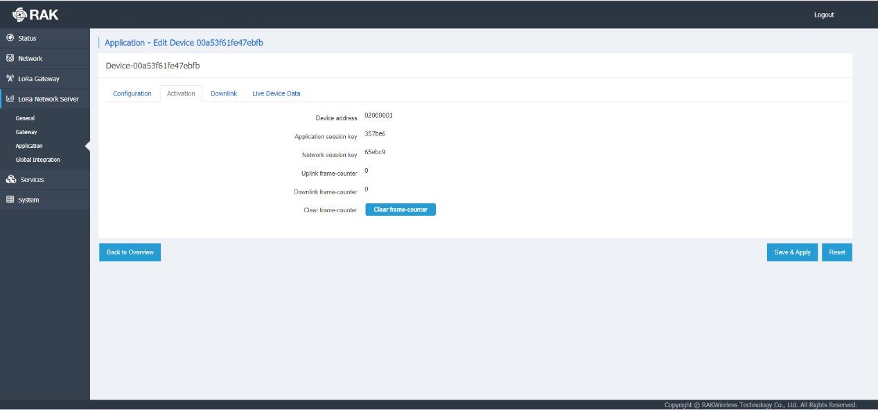
Figure 7 | Device parameter configuration
For the purpose of this example we are using the parameters in Figure 7 above. Thus, upon hitting the “Save & Apply” button your device will request to be authenticated.
If this is successful you should see the data in Figure 8. This would mean that your Device has successfully joined the network and its LoRa Frames will be properly handled (forwarded, decrypted, etc).
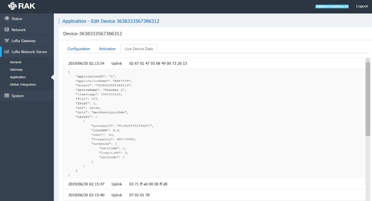
Figure 8 | Activated device parameters
If you go to the Live Device Data tab you can monitor the traffic of your Device. You can observe in real time the meta data and payload (provided the Device is sending Uplink Frames).
There You Go!!
We are going to end the tutorial here. To Summarize:
• You have a working Gateway with a full LoRa Server running on it now
• You have configured your first Application and added your first Device.
• You can see the data sent by the Device in real time.
This is a great start and a solid base for understanding how a LoRaWAN network works. Furthermore, as you have a working server you can now expand its functionality, by adding payload encoders/decoders, integrations, etc.
That, however, is a topic for another article. 😊